


F1: Aeroelasticity in the age of active aerodynamics
The wing of a Formula 1 car has one main job: create a pressure difference. Bernoulli’s equation explains how the pressure below the wing drops as its shape makes the air flow faster beneath it than above it. This lower pressure pulls the wing down and pushes the car into the ground. The extra downforce loads the tires, giving them more grip so the driver can go faster through corners. The wing’s purpose is to manage the load on the four contact patches, each about the size of a human hand, which are the only places where these 1,000hp cars touch the track. Everything the aerodynamicist, structural engineer and suspension designer does is focused on those four patches: increasing load when the car needs grip and easing it off smoothly when the car needs speed.
What the wing must now do
A wing that generates downforce also creates induced drag – the lift/drag ratio, which is the cost of redirecting airflow. At low speeds in corners, where tire load matters most, this trade-off is worth it. At high speeds, the reverse is true.
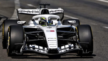
With the current rules, both the front and rear wings have movable elements. In straight-line mode (known as X-mode), these rotate to lower the angle of attack, which reduces downforce and, consequently, drag. In corner mode (also known as Y-mode), they move back to generate maximum downforce. Unlike older drag-reduction systems, moving both wings at once maintains balance between the front and rear, keeping tire loads more even and the car more stable.
“The magnitude of downforce defines the envelope the driver can explore, and it sets the outer limit of how fast they can go through a given corner,” explains former F1 aerodynamicist Jack Chilvers. “But what drivers are actually most sensitive to is balance. Where is the aerodynamic load sitting relative to the front axle versus the rear? In our experience, drivers prefer a slight front bias of just over 50% because it gives them the bite into the corner on entry. They want to feel the nose commit. So when you have a step change in the transition back to corner mode, it is not just the magnitude of the returning downforce that matters. The question is whether the front and rear returns occur at the same rate and in the same proportion. Any asymmetry in that transition shifts the balance at exactly the moment the driver needs most confidence in the car.”
The transition window lasts up to 400ms, which is the maximum allowed by the rules. During this time, the car’s total aerodynamic load changes substantially, and so does the load on the suspension. As the straight mode is engaged, the downforce drops, the suspension extends, the car rises and the ride height increases. When the wings switch back to corner mode, the aero pushes the car down again. Ride height is critical. As the gap between the floor and the ground changes, the speed of air under the car changes too, which affects the pressure drop and the center of pressure under the floor. If the car is pitching during this transition, the pressure field under the floor also changes, leading to fluctuating tire load and thus grip.
The structural consequence
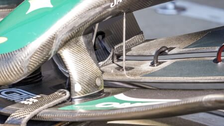
As aerodynamic load increases, every wing will bend to a degree. This is normal for any elastic structure under stress, and it is a characteristic that can be made beneficial, particularly with a wing made from carbon composites. If a wing skin is designed so that bending and twisting are linked, it will twist as it bends under increased load. That twist alters the angle of attack as the leading edge rises relative to the trailing edge, reducing downforce and induced drag as the load increases.
In aeroelastic terms, this is known as washout: a deliberate structural response that reduces the aerodynamic loading on the wing as it deflects. The concept is not new. The first controlled application of structural washout was demonstratedin a high-performance aircraft called the X-29, which featured a forward-swept wing where fiber orientations in the composite skin were specifically arranged to induce nose- down twist under bending load, preventing aerodynamic divergence. The principle has been refined continuously since, and in Formula 1 it has been exploited for decades despite the best efforts of regulators to limit its effect.
The washout effect grows with the square of speed, so it happens most when it is most needed. Even in the era of active aerodynamics, harnessing this passive, speed-based structural response alongside the active system remains valuable. The moveable parts rotate when commanded, but the composite skin starts to unload the wing before that rotation is complete, smoothing the entire transition.
“If you go from straight-line mode back to corner mode, the car sees a large and rapid increase in downforce,” Chilvers notes. “The suspension is going to respond to that, and in extreme terms, it will try to slam the car down. As the cars are pitch sensitive and ride-height sensitive, that load change does not just add grip; it shifts the peak pressure distribution beneath the floor as the ride height changes. If the composite structure softens that transition – as in, if the load builds more progressively before the full actuation arrives – you give the suspension a much more manageable input. The ride height settles rather than oscillates. And an oscillating ride height is an oscillating aero balance, which is the last thing a driver needs when they are already asking everything of the tires.”
The tire is where this all comes together. “Think about what that contact patch is being asked to absorb,” Chilvers continues. “You go from a relatively low-load condition in straight-line mode to full corner mode in 400ms. The tire has to respond to the increased vertical load while simultaneously generating lateral and longitudinal forces for braking and turn-in. That is a significant ask in a very short time. If the composite structure is doing any part of that work in advance, starting to bring the load back before the actuation fires, smoothing the gradient, then the tire has a more manageable transition. There is a meaningful difference between a load arriving as a wave and a load arriving as a wall.”
A team using this setup can also run the car lower during cornering. Because the passive aeroelastic response starts to unload the wing before the car reaches its highest straight- line speeds, there is less risk of the vehicle being pushed into the ground under peak load, which could wear through the required plank and risk disqualification. Running lower increases airflow velocity under the floor, deepens the pressure drop at the diffuser entry, and boosts downforce in corners, where grip matters most.
The material that makes it possible
Carbon-fiber-reinforced polymer is anisotropic, so its properties depend fundamentally on direction. A single unidirectional ply of intermediate-modulus carbon is more than 30 times stiffer along the fiber axis than across it, a degree of directionality that no metallic material approaches. But not all carbon-fiber material is selected for the same reason, and in a structure as load-complex as a front wing, that distinction matters considerably.
“From a fiber perspective, they generally fall into two categories,” explains Jamie Wheat, industry process expert at Dassault Systèmes and former head of FEA tools and strategy at Red Bull. “That’s stiffness-related or strength-related. Whether you’d use something like a T1000 or an M55J or M46J depends on the scenario you’re looking at. In something like a front wing, in the strength-critical areas, you would use a strength-dominated fiber rather than a stiffness-dominated one. And in the areas where you want stiffness, and you’re not necessarily worried about strength, you would use the stiffness-dominated fibers. It’s not uncommon to mix and match depending on what that region of the structure needs to do.”
Resin selection follows the same logic of matching the material to the environment. The front of the car runs cooler than the rear, and a resin system curing at 135°C provides a good balance between ease of manufacture and thermal resistance for most aerodynamic surfaces in free airflow. Components operating in higher-temperature regions – near brake ducts, for example – migrate to bismaleimide systems curing around 177°C, retaining stiffness where a standard epoxy would begin to soften.
The fibers themselves are delivered in pre-preg form: pre-impregnated with partially cured resin in controlled quantities. A front wing cannot be built from unidirectional (UD) tape alone. “You’ve got to have woven in there to take the shear loads, among other reasons,” Wheat notes. “Formula 1 teams have experience in terms of how many UDs in a stack they can use between woven layers, and they’ll stick to that relationship.” Woven fabrics in the 150-240g/m2 range handle the complex, curved surfaces of aerodynamic components without misaligning the fibers. Spread-tow fabrics, where fiber tows are opened flat before weaving, to eliminate crimp, can achieve areal weights as low as 43g/m2, meeting stiffness and coupling targets at reduced mass. Every gram saved can be redeployed as ballast, adjusting the car’s center of gravity and the front-to-rear tire load distribution.
Stack multiple plies at different angles, and the laminate’s mechanical character becomes a designed property. How it responds to forces and bending is described by three matrices: A for in-plane behavior, D for bending and B for the coupling between them. The bend-twist response that produces the washout effect is driven primarily by unbalanced laminates, which are those where the fiber angle distribution is not symmetric about the laminate’s reference axis, or by rotating the primary stiffness axis of the laminate relative to the wing’s own axis. This is a subtle but important distinction: it is not laminate asymmetry through the thickness that generates bend-twist coupling in the way most commonly understood, but rather the angular relationship between the dominant fibers and the structural axis of the wing. The bend-twist response emerges from the aggregate of every ply angle through the thickness, and particularly from the off-diagonal terms in the A and D matrices that arise when the laminate is unbalanced in this sense.
Designing the response
Choosing the right ply angles to achieve a target aeroelastic behavior is an optimization problem, and the simulation environment used to solve it has become considerably more capable than it once was. In the approach used by engineering teams today, CAD and structural simulation share a common data model, where a design change made in the geometry automatically propagates to the finite element model and reruns the analysis. What would previously have required a manual handoff between software packages now happens within a single connected environment, allowing engineers to iterate rapidly through laminate configurations and observe the structural consequence of each change in near real time.
The starting point for the structural simulation is the aerodynamic load field from CFD. A Reynolds-averaged Navier-Stokes simulation resolves the pressure distribution across every surface of the wing, including upper skin, lower skin and the slot regions between elements. That pressure field becomes the boundary condition for the finite element structural model. The solver calculates how the wing deflects, which updates the aerodynamic geometry, and the coupled simulation iterates until the airflow and structural solution converge. “The stiffness response of composites is fairly well defined,” Wheat notes. “It’s a complex material but it’s a fairly simplistic problem to solve. So if you’ve got confidence in either wind tunnel or CFD, then developing a wing to do something specific in terms of aeroelasticity should be relatively straightforward.”
The aerodynamicists, however, define the limits within which the composite engineer works. The wing’s external geometry, which is known as its wetted surface, belongs to the aerodynamics department, and changing it to suit the structural design is not generally an option. “So the only thing you can do is change the layup and the construction to incorporate the behavior at the load cases you’ve been given,” Wheat explains. “Typically, you would simulate several load cases, including high speed and low speed, to see what the wing does under those conditions, and then talk to the aerodynamicist about whether the level of back-on or back-off is what they’re looking for to change the aero balance between those two conditions.”
This back-and-forth between laminate engineer and aerodynamicist, mediated by a simulation environment that can predict the structural outcome of any laminate configuration, is how the wing’s aeroelastic response is arrived at. Optimization tools within the simulation environment can automate the exploration of laminate configurations against target displacement outputs, and AI-assisted design tools allow engineers to visualize the impact of design decisions in near real time, compressing an iterative process that once took weeks into something that can be explored in hours. Studies using this approach on F1-scale rear wings have confirmed that extension-shear coupled laminates, optimized through lamination parameters using response surface methodology, produce measurable induced drag reduction at high speed while cornering downforce is maintained at low speed, and that the gradient of the load change matters as much as its magnitude.
From model to measurement
Simulation establishes that the design is physically coherent. Wind-tunnel testing confirms that the structure built to the specification behaves as the model predicted, in a real aerodynamic environment where material variability, manufacturing tolerances and changing airflow are all present. But the confidence in the simulation itself has to be earned before either of those steps can be trusted.
That confidence begins with material characterization. “Teams would do specimen testing, developing their own material samples, and they might do batch-to-batch variation tests to calibrate materials,” Wheat notes. “If you’re trying to do anything complex, like coupling bend and twist, you would produce specific test items and take those ideas forward at a relatively small scale before moving to larger components.” The mechanical properties extracted from those specimen tests become the material data embedded in the simulation model. When the model predicts one behavior and the physical part delivers another, the investigation that follows is about understanding which assumption was wrong, not simply adjusting the design. “You’d want to know why there was a difference, rather than just reacting,” Wheat observes. “If you understand where the differences come from, you have a chance of capturing the same differences next time.”
Wind-tunnel testing contributes a great deal to the aerodynamic development of a Formula 1 wing, but its role in validating aeroelastic behavior specifically is more limited than it might appear. Tunnel testing is limited to 60% scale models and wind speeds up to 180km/h, meaning it is extremely difficult to simultaneously match both the aerodynamic load distribution and the structural stiffness of the full-size part. A component that replicates the scaled aerodynamic geometry will not replicate the scaled structural response, and a component tuned to match the stiffness scaling will compromise the aerodynamic fidelity. In practice, the parts that go into the tunnel are often machined aluminum or 3D-printed components rather than hand-laminated carbon, both for the speed of production that wind-tunnel testing demands and because a fully laminated composite part built to the correct ply schedule would be too slow and costly to manufacture at the pace of tunnel development cycles.
What the tunnel does deliver with confidence is the aerodynamic force data, including lift, drag and pitching moment across the speed range, along with the pressure distribution that feeds back into the coupled CFD-FEM model. That data is invaluable for refining the aerodynamic load field the structural model is working from. The structural response itself is validated through a different and more fragmented process.
Pre-season testing provides the most direct window into real full-size composite wing behavior under realistic aerodynamic loads, and it is here, with the car running at track speeds on representative surfaces, that teams can observe actual deflection behavior and compare it against simulation predictions. Strain gauges and on-car measurement systems capture load and deformation data that the simulation environment can then be correlated against. The result is not a single clean validation event but an iterative process of simulation, track observation and model refinement that builds confidence in the coupled CFD-FEM approach over time and across development cycles.
The manufactured wing
The aeroelastic response depends on the lamination parameters, and the lamination parameters are only realized if the finished wing matches the designed ply angles. A consistent angular error across several plies shifts the coupling terms in B and D away from their targets, changing the passive twist response and delivering a load gradient that the suspension was not set up to manage.
Plies are cut to net shape by CNC machines from digital flat-pattern data and hand-laminated into female composite tooling under clean-room conditions, often with the aid of laser projections for positioning, with vacuum de-bulking applied at intervals to consolidate each stage. The autoclave typically cures the part at around 7 bar at the specified resin temperature, achieving a fiber volume fraction of 55-65%. Sandwich constructions where thin CFRP skins are formed over aluminum or Nomex honeycomb cores are processed in staged cure cycles, with the outer skin cured at full autoclave pressure and subsequent stages at lower pressures that the core can tolerate.
Precision on placement
The simulation environment extends into this manufacturing process. Producibility analysis tools allow engineers to simulate how fibers actually orient themselves during a hand layup on complex-curved tooling, identifying where fiber paths deviate from the theoretical and what that deviation does to the structural properties the model specifies.
“We have the capability of simulating a hand layup component and looking at where the fibers actually go rather than the theoretical,” Wheat explains. “While the person in the clean room must make it as you’ve simulated it, that reliance is managed through close collaboration between the laminator, the composite designer and the simulation engineer, working together in real time on the shop floor. Where the layup deviates from the simulation, the conversation between those three disciplines resolves it on the spot, feeding the adjustment back into the model so that the as-built part and the predicted behavior remain aligned.
“It is a genuinely collective process, and the fidelity of the finished wing to its designed aeroelastic response depends as much on that collaboration as it does on the quality of the simulation or the skill of the individual laminator. Whenmaterial calibration is thorough and that collaborative discipline is maintained through the layup, the simulation earns its status as a reliable design instrument, and any remaining discrepancy between predicted and physical behavior points the engineering team toward a specific and addressable cause rather than an unexplained gap.”
The system thinking behind the wing
When the wing is fitted to the car, it becomes part of a system where aerodynamic surfaces, suspension and tires all work together to manage the vertical load on the tire contact patch. The wing creates this load, the suspension transfers and adjusts it, and the tire converts it into grip, which lets the car change speed and direction quickly.
The active system switches the wing between modes. The composite skin begins that transition on its own, smoothing the load before the actuated elements have finished moving. The suspension accommodates this gradual input and keeps ride height more stable, maintaining a consistent pressure field beneath the floor. With a load that rises and falls as a wave rather than a wall, the tire holds its grip and gives the driver confidence to go faster.
The wing tips tell their own part of the story. “The wing tips can twist back and drop away at speed, and it’s not just about the load on the wing itself,” Chilvers notes. “The vortex shedding position changes with the wing geometry. As the tip twists and the center of pressure shifts, the shed vortex weakens because the load that generates it has decreased. A weaker, repositioned vortex at high speed that strengthens and returns to position as the car slows into a corner is a passive aerodynamic response to operating conditions, built entirely into how the composite was constructed.”
Everything from fiber type and resin chemistry to ply angles, lamination parameters, coupled CFD-FEM optimization and wind-tunnel validation is made with the goal of ensuring the wing delivers load to the tires as consistently and controllably as possible at every moment of every lap. The simulation environment that connects every step of that process, from first design intent to validated physical behavior, is what makes the aspiration achievable in the development timescales Formula 1 demands. “The key,” Wheat says, “is always learning and capturing the engineering knowledge that comes out of that process, so it’s accessible when regulations change, when the design evolves and when the next set of problems needs to be solved.” In the end, a Formula 1 wing is a tire load management system, built from carbon and resin and tested in the digital world long before it turns a wheel, and oriented precisely to give the driver the confidence that the car will respond exactly as needed, right when it’s needed.
Simulation specifies the fiber angles in a layup. The manufacturing process must deliver them. And it is here that a newer approach to composite preform production is beginning to change what aeroelastic tailoring can achieve in practice. Conventional automated fiber placement steers fibers by bending the tape, a process that introduces wrinkling and residual stresses that alter local laminate properties at precisely the points where the designer most needs accuracy. Rapid tow shearing, developed through research originating at the University of Bristol and now deployed industrially, takes a different approach: the fiber tape is sheared rather than bent during deposition, maintaining equal fiber length across the tape width and eliminating the wrinkle and residual stress that bending introduces.
The practical significance for aeroelastic tailoring is direct. “By steering plies, it is possible to introduce larger coupling values than with standard laminates, while also fulfilling strength requirements as the material is used more efficiently,” explains iCOMAT’s Dr Olivia Stodieck, a composites engineer and lead researcher on tow-steered aeroelastic tailoring, whose doctoral work at the University of Bristol established the numerical framework connecting variable-stiffness laminates to wing aeroelastic behavior. “With fiber steering, we have more design freedom to achieve both structural strength and stiffness requirements. This means we can usually achieve better- performing designs, or lighter designs, without having to introduce pad-ups.”
The angular precision that the shearing process achieves is fundamental to realizing the designed coupling behavior. “We typically aim for ±2°,” Stodieck notes. The significance of that tolerance lies in where the angular sensitivity is highest. “Deviations in the 0° fibers that resist most of the bending loads in wing structures will have the largest effect on the bend-twist coupling behavior.” A 2° error in the primary load-carrying fibers propagates through the laminate stiffness matrices and shifts the coupling terms away from their design targets. At ±2°, that shift is manageable and predictable. Wider tolerances, typical of manual layup, are not.
Where the fiber path specification changes as a design evolves (as it does repeatedly through a Formula 1 season to tailor the car to each track), the tow shearing process allows updated manufacturing instructions to be generated from a revised design with minimal manual rework. Forming simulations predict the fiber path deviations that will occur when a flat preform is shaped over compound-curved tooling, and the finite element model is updated with the as-formed fiber angles rather than the theoretical flat-preform angles. For wing skin geometries, which are typically mildly curved, the forming deviations are generally less than 10°, and their effect on the structural predictions can be accounted for before the part is built.
Fiber steering also changes the stress concentration picture. Conventional laminates accumulate stress around discrete features such as cutouts and fastener holes, because the 0° fibers that carry the primary bending load are severed at those locations. Steering allows those fibers to be routed continuously around the feature, maintaining load paths that a straight-fiber laminate cannot achieve, and reducing the peak stress at the very locations where crack initiation is most likely.